

Filament Tolerances
Filament Tolerance is arguably the most important quality to look for when choosing a plastic supplier.
Filament precision is everything when making a quality 3D print. A printer with a good extruder can produce high quality prints over a wide range of plastics. What a printer cannot do, is account for changes in filament diameter. The finest calibration and most carefully crafted printing profile means nothing when your extruder pulls in filament that is slightly thicker or thinner than expected. The surface quality of your print suffers, extruders jam, and prints can fail.
When examining the quality of filament there are two things to look for; the Precision of the Diameter to which the plastic is extruded and the roundness of the filament. You should find filament that is both consistently round and consistent in its diameter along the length of the spool.
Filament is visibly poor.

Proper filament is round and very consistent.

The out of round filament (shown first) is 3mm Natural PLA Filament we obtained as a sample while searching for suppliers. It was known the plastic was intended for 3d printing and that high tolerances were required; we were assured it was adequate... It was not. The filament is visibly poor in quality, with wide ranging diameters and a cross-section far from circular. Attempting to print with this filament (we did) will bring about heart ache and pain. Calibration is a nightmare, and printing from an extruder that uses a Delrin plunger (All Makerbot's Extruders and the Ultimaker use these) caused stalls and jams galore.
The second image is how 3d printer filament is supposed to be (A sampe of our own Precision 3D Filament). It is also 3mm Natural PLA but plastic has been extruded with very tight tolerances. It is very round, with little to no measurable deviation in diameter. Printing with this filament will produce superior prints and print smoothly through miles of plastic.
Tracking Diameter Error
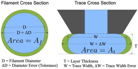
For a printed object to look nice, be structurally strong, and have the appropriate dimensions your printer needs to know exactly how much plastic it is pulling through the machine at any given time. While tolerances are usually given as a possible plus/minus change in filament diameter, it is the Cross-Sectional Area of your filament that determines the right amount of plastic to extrude and from that the end quality of your prints. Knowing the area of your filament as well as how fast it is moving into your extruder (commonly Flow-Rate in mm/s) allows the printer to know the volume it is pushing out of your extruder per second at any given instance. This coupled with how fast the nozzle of your extruder is moving relative your print-bed (or Feed-Rate in mm/s) allows us to make a connection between the Diameter (and error thereof) of our filament and its affect on the quality of our printed objects. The cross-sectional area of our filament is directly proportional to that of a printed trace.
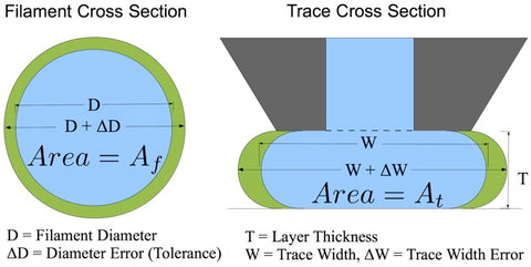
Δ is the capital greek letter Delta and in this case indicates error. ΔD is equal to the tolerance of filament. Green indicates the excess plastic taken in by the extruder and laid down by the nozzle. Here a trace width is approximated as a rectangle with hemispherical sides. Because the plastic in the trace cross section on the right of the diagram is constrained by both the top and the bottom, an excess or deficiency of plastic affects only the printed trace width 'W.'
The error in trace width is actually a hair more than twice that of the diameter but this is close enough for our purposes. Because this error is measured as a percentage of the diameter, the same tolerances on smaller diameter plastic will have a greater percent error and consequently lead to greater differences in trace width area. Identical tolerances for both 3mm and 1.75mm filament will result in nearly two times the error for 1.75mm. It is also worth noting that different types of thermoplastic are prone to have greater or lesser error due to the difficulty in extruding them. PLA for example is more difficult to extrude than ABS and as such one is able to get ABS with much tighter tolerances. Pigmentation can have an effect as well. Extrusion lines using laser micrometers to track filament diameters have a harder time with natural resins than they do with colored plastics.
Poor Filament Reduces Surface Finish and Quality
One of the most obvious visual differences between objects made by a 3d printer versus those made by other manufacturing methods such as injection molding is the difficulty in producing a smooth glossy finish on a printed object. A well tuned printer with high tolerance filament is capable of producing surprisingly smooth surfaces; poor calibration or substandard filament can reduce the quality of both the feel and appearance of prints. The figure below demonstrates how error from the filament causes the edges of a print to be misaligned.

Here we see traces that have been affected by the maximum positive and negative error allowed for a given tolerance. Positive error will push an edge out about twice the distance of negative error; this is from the inside edge of the trace running into previously laid down filament where extra plastic has nowhere to go but to the outside wall of your print. As such, one will find that laying down too much plastic will more often produce visually poor prints, while laying down too little plastic will produce objects that are structurally poor and prone to breaking and de-lamination (layers and traces coming apart.)
Poor Filament Causes Extruder Drive Failure
Filament that does not have a good circular shape or that has an irregular diameter does not only produce poor looking prints; it can also be a hard to diagnose cause of total extruder failure.
Especially susceptible extruder types are those that use a plunger to apply pressure to filament during extrusion. In normal operation the pressure from the plunger pins the filament to the drive gear with enough force so that the teeth are able to bite into the filament driving it through the extruder's hotend. The plunger is usually held in tension by an adjustable screw that is tightened or loosened to apply the appropriate amount of pressure. Pressure is applied to the filament such that the drive gear is able to grip while minimizing the amount of friction between the filament and the plunger. Below is a top down view of a properly tensioned plunger type extruder.

However, because the tension must be done by hand, irregular filament causes the tension to change leading to two different possible failure modes.
On the left a greater diameter of filament between the plunger and drive gear has lead to excessive friction between the filament and the plunger. This friction will either be too great for the motor driving the filament and it will cease to turn (listen for a "clunk" "clunk" sound), or the force needed to push the filament will overcome the integrity of the plastic and the drive gear will tear pieces directly off the filament to the point that there is nothing left to grip (stripping).
Meanwhile, on the right side of the figure the non-circular filament has slowly rotated and circular filament with poor diameter control have cause the drive gear to lose its grip all together. The plunger no longer pushes the filament into the drive gear with the needed pressure for the drive gear to gain traction. The drive gear will spin merrily away leaving your filament still and unmoving.

Points to Consider
Hobby printers have advanced a tremendous amount over the last couple years (months even). Make sure your filament is advancing too and find a good filament supplier (we're perhaps openly partial to this one.) Some points to leave by:
- High quality filament will lead to stronger and better looking prints
- Poor filament can lead to poorly printed objects and extruder failure
- High quality filament is round and has a low +- tolerance value
- A 3% variation in diameter will lead to a 6% variation in printed trace width
- 1.75mm filament with the same tolerance as 3mm will have nearly 2 times the error
- Large W / T ratios will have greater absolute trace width error than low ratios for the same layer height
unEwOYVb
zLBXHDAZGCnjupP